
Most MX5s left the factory with an open differential. Obviously, this is no good if you want to drive fast, race or drift. Fortunately, there are options to fix this. The easiest route would be to purchase a used Torsen unit from a breaker, but these should be inspected for wear and if you are converting a 1.6, you also need a 1.8 propshaft and driveshafts.
Alternatively, there are companies out there (Kaaz, OS Giken, Quaife, Blackline etc) that make differential carriers of varying types that you can swap into your existing open diff to convert it into an LSD. This is the route I decided to take, and I chose to use an Ashcroft unit.
The Blackline, Ashcroft and the Quaife are helical ATBs. These are very similar in operation to the Torsen Type 2, but with the added bonus of being brand new. Swapping any of the different types you can purchase into an open diff should be this same procedure. However, if you get any manufacturers instructions, make sure you read them to identify any special requirements there might be.

It is worth noting, that all of the available diff inserts on the market will only fit a 1.8 differential. This is because 1.6 diffs used 6″ ring gears, while the 1.8 used far stronger 7″ ring gears. If you intend to run anything more serious than stock power you should consider upgrading to the larger 1.8 unit for reliability.
This mod is well within the abilities of a competent DIYer, but it does require some specialist measuring equipment to correctly set the gear backlash and the bearing preload. Remember to take your time and double check everything as you go along.
Before we get started, let’s go over what you need to complete the mod and the assembly specifications.
Special Tools
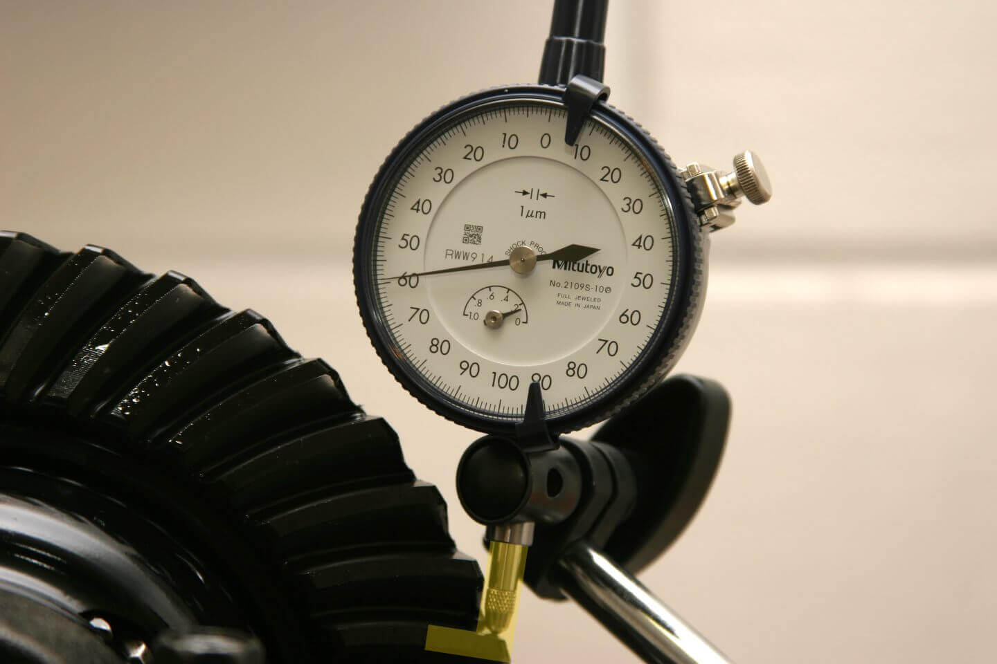
I used Mitutoyo measuring equipment with a resolution of 1 micron, but that’s overkill for this job. A resolution of at least 0.01mm (or 0.001″ if you are so inclined) is all you need and the torque wrench needs to be capable of a range that encompasses 18-83 Nm (14-61 ft-lb). There is no need to spend the earth on top end gear, as long as it meets the minimum requirements in the table below, it will work fine.
| Tool | Range / Resolution (Metric) | Range / Resolution (Imperial) |
|---|---|---|
| Dial Indicator | 1mm / 0.01mm | 1″ / 0.001″ |
| Micrometer / Calipers | 175-200mm / 0.01mm | 7-8″ / 0.001″ |
| Torque Wrench | 18-83 Nm | 14-61 ft-lb |
Additional Parts
This table lists all of the parts you will need in addition to the diff centre of your choice. It is possible to buy the genuine Mazda part for the carrier bearings, but I chose not to. Instead, I purchased bearings of the same dimensions from a high-quality manufacturer. This generic part number is included in the table should you wish to go the same route.
| Part | Quantity | Mazda Part Number | Generic Part Number |
|---|---|---|---|
| Side Seals | 2 | MA02-27-238A | |
| Carrier Bearings | 2 | 0221-27-350 | 32008 |
Torque Specs
These values came from the 1995 workshop manual and are all specified as a range of acceptable torque values. The torque value I used is in parentheses and my primary torque measurement unit is Nm.
| Part | Torque (Nm) | Torque (ft-lbs) |
|---|---|---|
| Ring Gear | 69-83 (80) | 51-61 |
| Bearing Caps | 38-51 (45) | 28-38 |
| Adjuster Lock Plates | 18-25 (20) | 14-18 |
| Case Bolts | 23-26 (25) | 17-19 |
Backlash and Preload Specs
| Measurement | Spec (mm) | Spec (Inches) |
|---|---|---|
| Backlash | 0.091-0.110mm | 0.0036-0.0043″ |
| Preload | 185.430-185.498mm | 7.3004-7.3031″ |
Disassemble the Differential
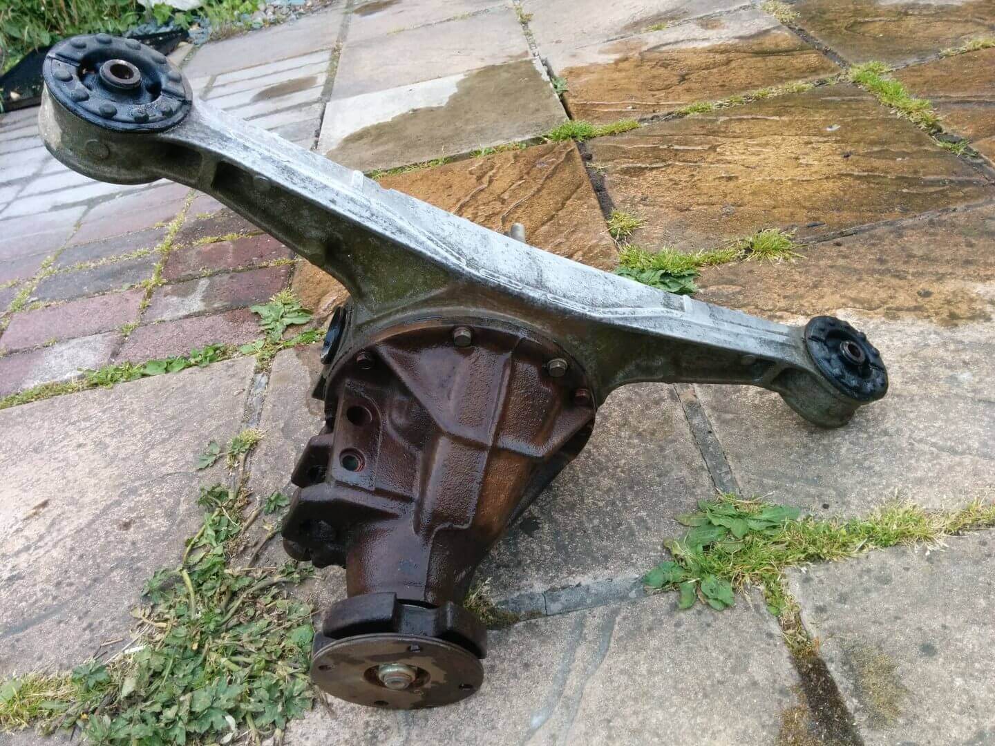
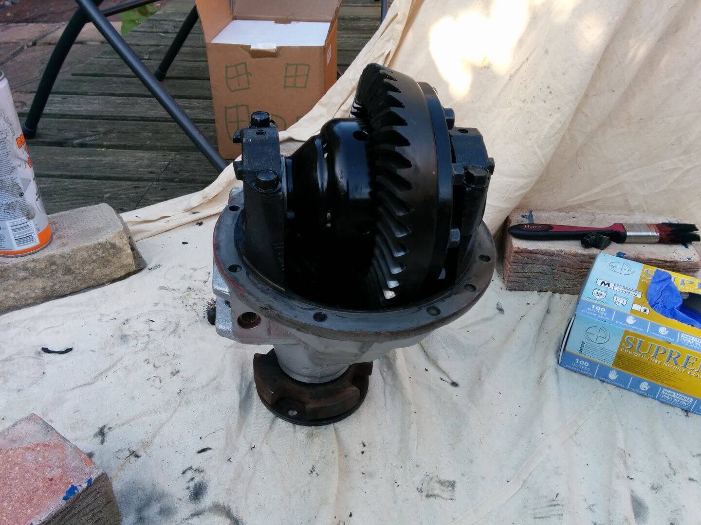
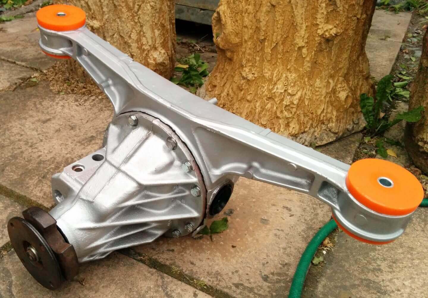
I started with a rather sad looking open differential that had been laying around outside for a while. The first step is to split the case so you can access the internals.
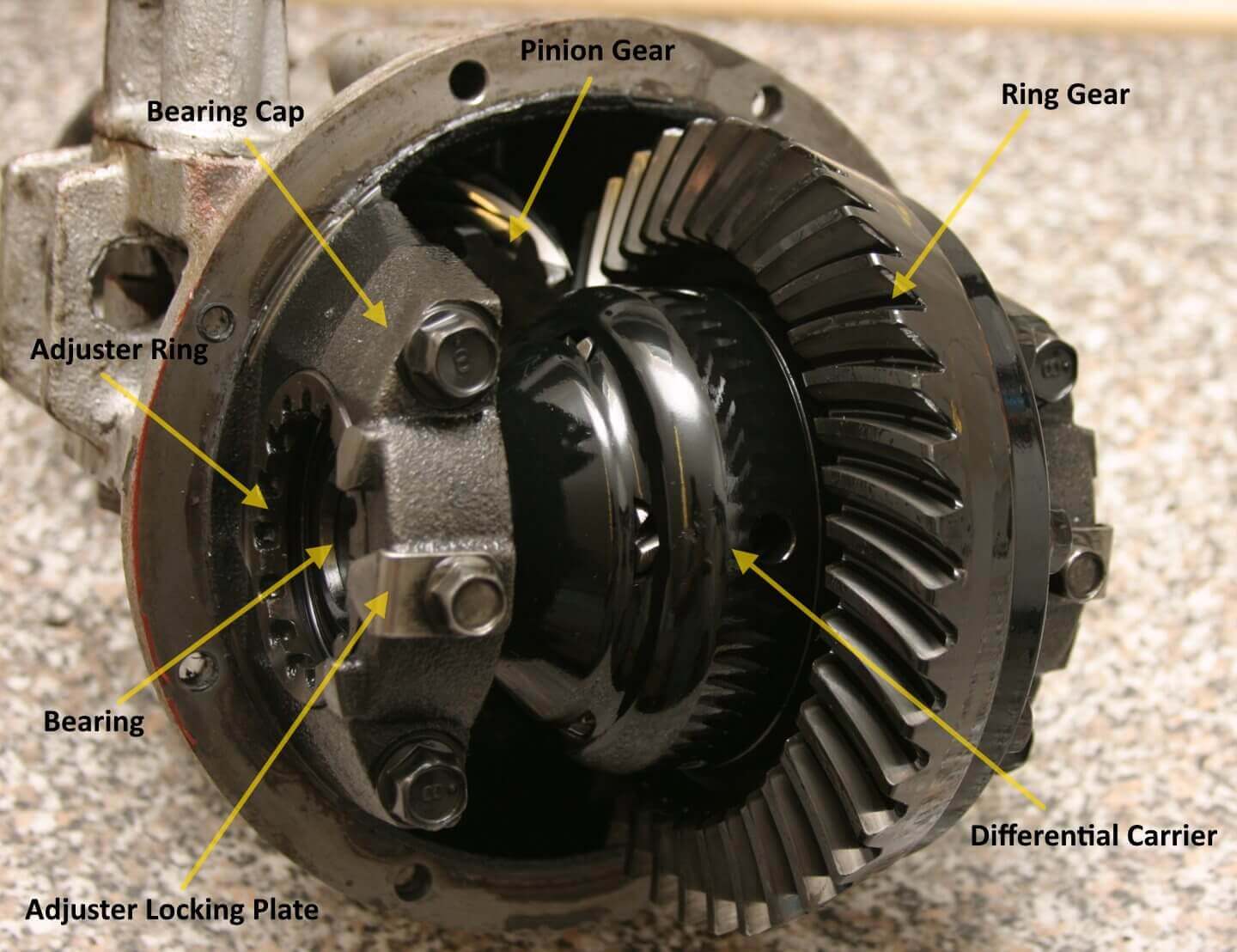
The differential housing and the pumpkin are held together with 10 M8 bolts. There are 3 lengths in use, 40mm, 75mm and 100mm and each bolt also sports a spring washer. Simply remove these and carefully lever off the pumpkin (this might require a few love taps with a rubber mallet). The two parts are joined together with a gasket material that will need to be completely removed from the mating surfaces. You should be faced with something that looks like this:
First, remove the adjuster locking plates and the bearing caps that are holding the diff carrier into the housing. You should be able to just lift out the adjusters and the carrier with little more than a wiggle. It’s easiest to lift out if you put your fingers through the bearings and pull straight up. If for some reason it still gives you a bit of trouble, tap the ring gear with a soft faced hammer to free the carrier.
The ring gear itself is bolted to the carrier by 10 bolts. These bolts do have loctite on them and may offer some resistance, a helper, a vice (cover the jaws to protect the diff) or an impact gun will make this job much easier.
You do not need to remove the pinion gear to convert an open diff to a limited slip. Take the time to give all the parts a thorough clean and remove any remnants of old loctite from the ring gear and its bolts.
The pumpkin has a little breather on the top of it that is protected by a baffle on the inside. Ensure that the breather is unblocked and give everything a clean behind the baffle. I also gave everything a coat of paint while it was all apart and changed the mounting bushings for a pair of Poly Bushes.
Replace the Seals
While the differential is apart, it’s the ideal time to change the side seals in the pumpkin. To change them, simply knock them out of the pumpkin from the inside and take the time to clean out the seal seats (especially if they were weeping). The new seals have a ‘cup’ of rubber on one side, this needs to be on the outside when installed. It’s easy to get them in with just a large socket and a hammer – do not use much force, they will slide in easily and be careful not to disturb the ring of grease on the seal. They are fully seated when they bottom out.
Assemble the Differential
It is very unlikely you will be able to get the original bearings off the diff carrier without damaging the race or retainer, so replacing these is a must. Installing the new bearings onto the new diff carrier is pretty simple, but would be made infinitely easier if you have access to a press. I ended up placing the bearing carefully onto the shaft making sure it was square, laying a block of wood over it and tapping firmly with a big hammer until it started to move, all the time making sure the bearing was not going on at an angle. When the bearing is about a quarter on it will no longer be able to tilt, so switch to a very large socket (one that fits perfectly on the race, but does not contact the bearing retainer at all) and bash it home. When it bottoms out on the carrier stop bashing – you don’t want to risk warping the race or damaging any of the edges. Repeat this process on the other side.
Install the ring gear onto the diff carrier by carefully dropping it over and aligning the bolt holes. I needed to tap the ring gear home with a rubber mallet (never hit the gear with a steel hammer – you don’t want to damage the teeth). Apply some blue loctite to the bolts and tighten them up in a cross pattern. Torque the bolts in 3 stages using the same cross pattern. As per the table at the top of the page, the torque I used was 80 Nm, so to get 3 stages I did 25 Nm, then 50 Nm and finished it off with 80 Nm.

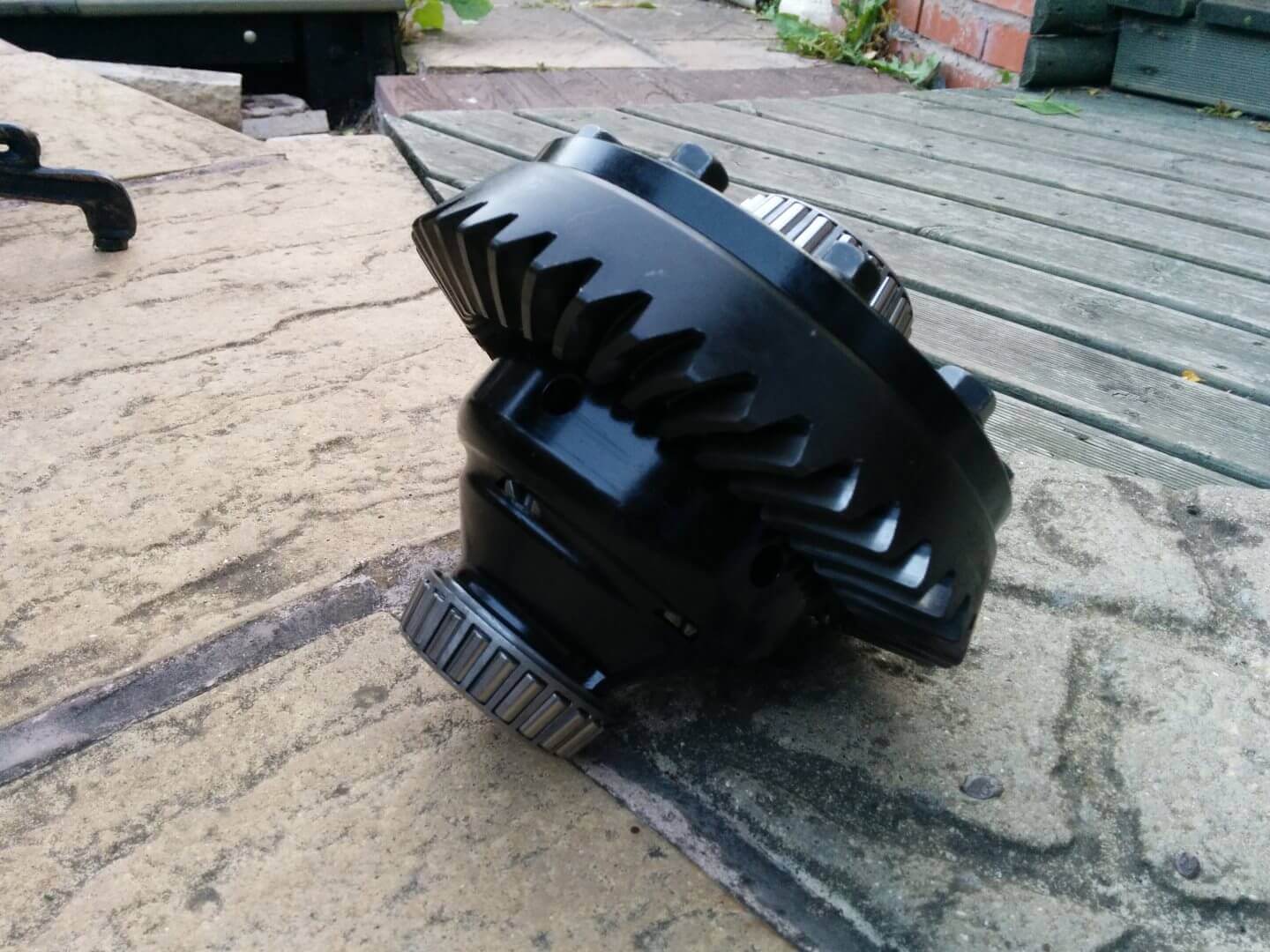
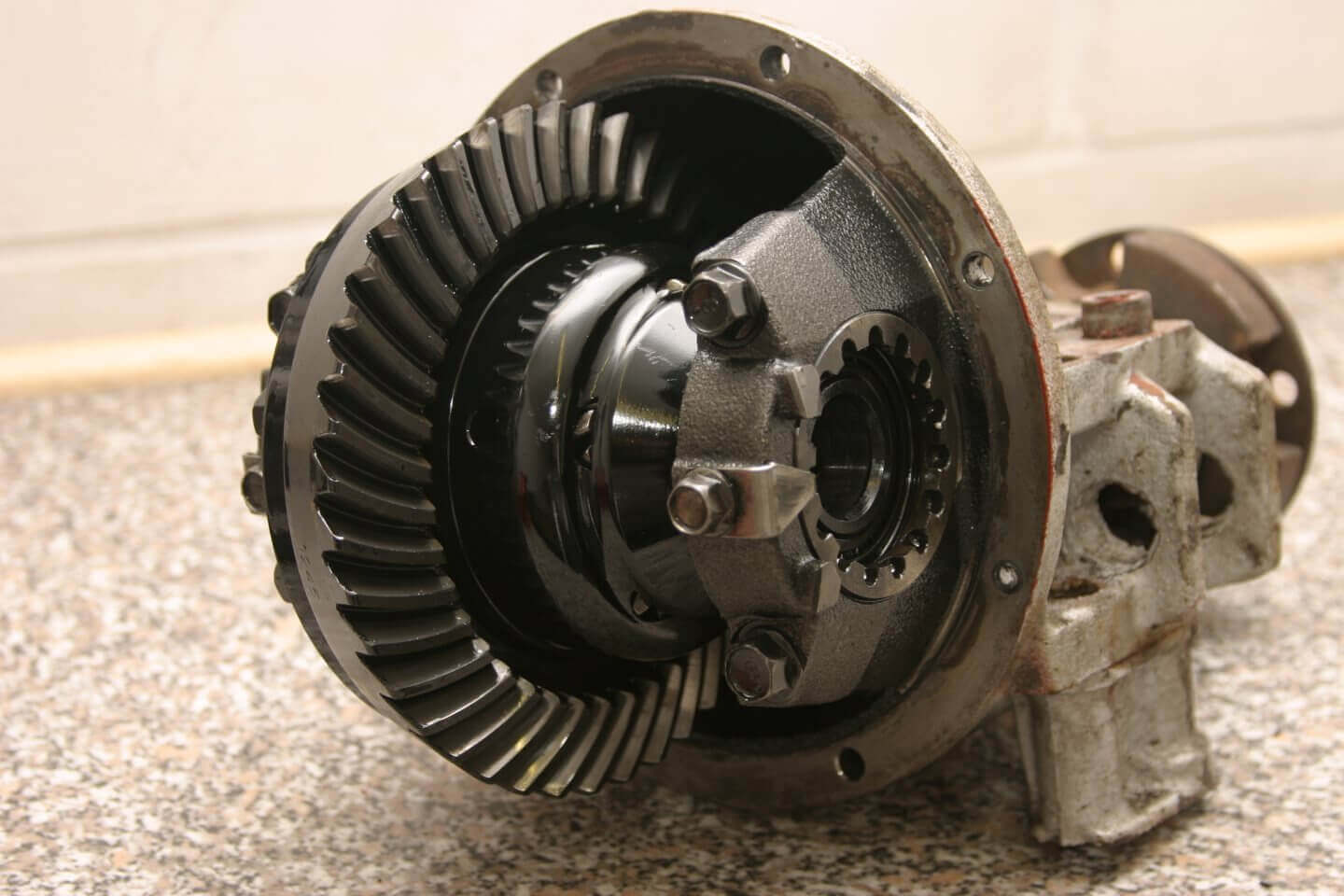
You should now have a new diff center that is ready to install into its housing. This is the perfect time to stop and admire it before it gets hidden forever.
I took the time to smear some gear oil all over the exposed bearing rollers just to ensure they wouldn’t ever run dry. The easiest way to install the carrier is to stand the housing on its nose so the opening is facing up, then simply hold the outer bearing races in place and lower it in. It should mesh with the pinion gear pretty easily with just a gentle wiggle and the races should end up seated on the smooth portion of the bearing carriers. Putting the carrier in place will make the thing very top heavy, so be sure it doesn’t fall over! The bearing preload adjusters also need to go in now. Simply push them onto the threads near the bearing.
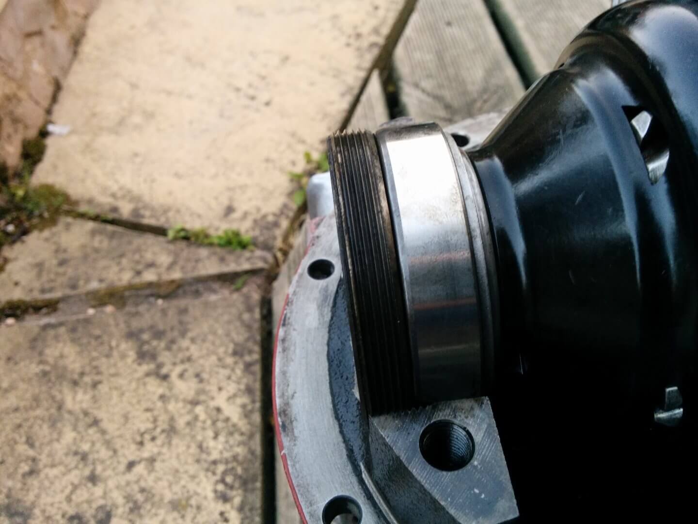
Pop the caps on, thread the bolts in just finger tight and check the adjusters aren’t cross threaded or fouling on anything. Snug up the bearing cap bolts, but don’t torque them down yet – save that for after the backlash and preload adjustments have been made.
Setting Backlash and Bearing Preload
This is the most important step of the build. Getting it wrong here can wear out the bearings or break the diff gears very quickly, so it’s important to take your time and double check everything as you go. Having said that, it’s actually a really simple process to get right.
The gear backlash and bearing preload are set at the same time by winding the 2 adjustment rings inwards. To move the adjusters simply use a parallel pin punch or other flat tipped punch and a hammer and tap it in the direction you want to go.
First tap the ring gear side adjuster in all the way until the ring gear contacts the pinion (you don’t need to mash them together, just snug them up) to give you near zero backlash.
Next set up the dial indicator on a stand and position it to measure backlash. Ensure the measuring plunger on the indicator is exactly perpendicular to the tooth on the ring gear that you are measuring and that the tooth is surgically clean, or you won’t get an accurate reading. Lock the pinion shaft so it can’t turn when you attempt to rock the ring gear back and forth against the pinion (I just clamped the companion flange to my bench).
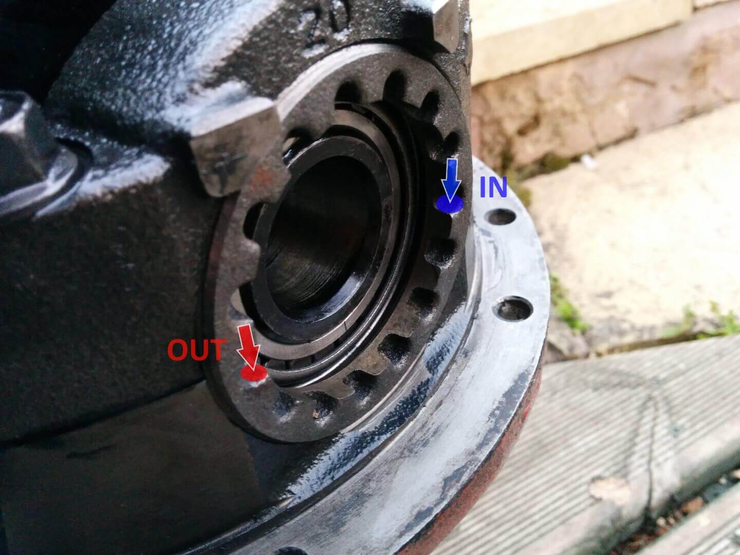
In order to test the backlash, grab a tooth on the ring gear between thumb and forefinger and rock it left and right (blue on the picture below). As you rock the ring gear back and forth, you will feel it bump up against the pinion gear teeth, this is backlash. In order to measure it, move the ring gear all the way anti-clockwise until it hits the pinion and make a note of the reading on your dial indicator. Now move the ring gear as far as it will go clockwise and note down the reading on the indicator. To get your backlash, simply subtract the 2 readings and check if its within spec. For example:
- Reading 1: 0.240mm
- Reading 2: 0.141mm
- 0.240 – 0.141mm = 0.099mm

Take your time and measure the ring gear in at least 4 places (imagine the gear is a clock, measuring at 12, 3, 6, and 9 should be a minimum. Refer to the yellow boxes on the picture above). If your backlash measurements are not within spec, keep winding the adjuster opposite the ring gear in until all of your measurement points produce readings that are within spec.
When all backlash measurements are within spec, check the bearing preload is also set correctly. This is done by measuring the distance between opposing diagonal faces on the bearing caps using a micrometer or deep reach calipers. If the reading is out of spec continue moving the adjuster that is not on the ring gear side.
IMPORTANT: Always check backlash again if you move the adjuster.

If you find that you can’t get both sets of measurements to sit within spec at the same time, try moving the ring gear side adjuster a small amount. Winding it in will tighten the backlash and preload, winding it out will loosen it.
| Measurement | Observation | Explanation |
|---|---|---|
| Backlash | Less than spec | Ring and pinion too close together |
| More than spec | Ring and pinion too far apart | |
| Preload | Less than spec | Preload is too low |
| More than spec | Preload is too high |
When all of the measurements are within spec, torque the bearing cap bolts and install the adjustment ring locking plates. If, like me, you didn’t ensure the adjusters always had a gap at the 12 o’clock position for the locking plates to seat into, swear profusely and repeat the adjustment and measurement steps until it’s all within spec and you can seat the locks.
Final Assembly
All that’s left to do now is run a bead of black RTV along the mating surface of the pumpkin and bolt the case halves back together. As always with RTV, let it skin over slightly before mating the two pieces together. Make sure you use spring washers on all of the bolts during assembly and do not over tighten them – You do not want to strip the threads in the aluminium pumpkin. The correct torque values for this are in the table at the top of the page.
That’s it, job done. Bolt it back up to the car and test it out at your nearest Oasis of Oppo!
So is it worth all this effort?
The short answer is yes. So much yes.
Going from an open differential to an LSD has a profound effect on the way the car handles. Most notably, it is now actually possible to power out of a corner! That may not sound like much, but it makes one hell of a difference to both your lap times and the amount of fun you can have.
Any of the LSD Options available for the MX5 will provide this feeling. The Ashcroft Transmissions built unit I used performs faultlessly. Most of the time I don’t even notice its there (believe it or not, that’s a good thing) and when I want to take a corner or roundabout with attitude, it’s always willing to play.
The poly bushes I used in the diff mounting holes noticeably increased the amount of vibration coming through the car from the rear, which may be objectionable to some (not me though, I have a very high tolerance for NVH). They have however, completely eliminated any and all gearstick wobble common to MX5’s when engine or diff mounts age. Jumping on the throttle aggressively also produces a noticeable ‘kick’ from the back of the car.
I love it.


12 comments
I just purchased a secondhand Torsen to replace my Fuji 1.8 because it started to make a ‘cloinking’ sound.
Now, would you recommend to replace the bearings as well as the seals? I don’t feel really comftorbable with setting the preload and backlash.
The Torsen should have about 140.000 KM on it.
are the differential bearings the same 6″ as 7″ I have a 6″ differential and do you have the bearing in question or a maintenance set with all bearings and seals, what is the price
I’m afraid we don’t currently offer a solution for the 6″ differential
Awesome! Keeping an eye on it then, definitely on my to buy list
Great read, may i ask how is the diff holding up? I can’t find much about them online so I’m really curious.
Cheers!
Took over 4 years of beating without issue over 300bhp
Awesome Cheers! Yes it’s a 1.8 diff
I’ve got a 2000 mx5 with an open diff, will a torsen lsd fit into the housing/will I be able to do what you’ve done here with an original T2 Torsen?
Hi Eryk, A Torsen LSD will fit into an open diff if your ring gear is 7″. In this post, we put an Ashcroft ATB into an open diff case because it was a 7″ ring. James.
Hi there, I rebuilt a diff from a mk2 1.8 automatic to put in my mk2 and for some reason the CV joint housing is wearing into the aluminum casing on the diff. Any suggestions on why this might be happening? Ive taken external measurements of both of the casings and everything seems to match up.
Thanks,
Muir
Great article!
Can you tell me whether the 1.6 and 1.8 miatas (both 2001+) had the same sized differential? I only know that the early 1.6 NA had the smaller size 6″. So it is not straightforward for me whether it was changed in the second gen NB-s or not. I would do this internal diff swap if I knew it has the bigger sized, more durable differential.
Thank you
Hi Adam,
All diffs in NA 1.6 95 onwards and NB 1.6 and 1.8 are 7 inch.