In this blog post we’ll be covering specifics of how to set up ‘boost control’ on your Turbo MX5/Miata but we’ll go into a lot of theory and detail about the how and why of it all, which is applicable to any turbocharged engine.
How to control the boost on your turbo MX5 (and most other cars)
There are several ways of managing the boost levels in your car, however, some of it depends on physical limitations of the system as a whole. We’ll take you through some of the core concepts first so that when we talk about ‘closed loop boost control’ and different wastegate springs, actuator arm angles and all that – it’ll make a lot more sense.
Firstly, what even is Boost Control?
A point here to keep in your mind about boost, is that its a measure of the resistance and restriction in the system, from the turbo outlet effectively to the tip of the exhaust.
If the system is incredibly free-flowing, theoretically there could be a scenario where it makes a bunch of power, with a big enough turbo, without making any boost pressure at all – that’s because we make power by pushing more air through the system and that’s exactly what a turbo does.
*To go into more detail on this, read this blog – pressure is required in order to flow more air, but volumetric efficiency maxes the most of what the engine can physically pump.
It’s a little more complicated when we talk about ‘Charge Density’ but let’s just say that 20psi on a baby turbo, isn’t the same as 20psi on a big turbo and it’s not the same in different weather conditions, with different sized intercoolers etc.
Anyway. Boost Control. Well, with an engine that’s being forced to consume more air, it’s going to increase the pressure in the system. We can control how much air is being consumed by lowering the boost pressure into the engine – effectively how much air the turbo is pumping.
We do this by Wasting some of the exhaust gasses that are coming out of the engine and being used to spin the Turbine.
A little tangent here, the turbo has a Compressor and a Turbine, 2 wheels also known as a hot side and a cold side. Exhaust gas enters the exhaust housing of the turbo, and is directed in such a way that it spins the wheel and is then ejected out the back into the downpipe and exhaust stream. Imagine a tornado, where the tornado touches the ground is the exit of the wheel.
The more gas that goes through this, the faster it spins, and as it’s connected to the compressor the faster that spins – which is sucking air in, basically the opposite of the turbine. It sends it out the compressor into the engine.
Turbines and Compressors are effectively mirrors of each other.
Knowing that, you might imagine there are 2 ways of controlling the boost – either at the compressor side (dumping the additional air that’s been generated), or at the turbine side, (stopping it spinning the turbine and in turn the compressor so fast and in turn generating less airflow).
While this is true, there are drawbacks of each method.
Turbine Side Boost Control
This is the standard way it’s done, either by an Internal Wastegate (wastegate flapper) that has an arm on the housing itself, that is controlled (actuated) by a wastegate actuator, or an External Wastegate (which is typically vac controlled and is not mechanically connected to the turbo by an actuation arm, and is physically situated externally to the turbo, i.e. in the exhaust manifold).
Both systems need to be designed efficiently in order to perform optimally, inevitably the limitations of an internal system is size which is why at a certain point of airflow, you must use an external gate which can be double the size and allow for double the flow of wasted gasses.
However, if the wastegate flapper isn’t in the optimum position and with the hole only being so large, that can limit the overall flow through the wastegate which limits the minimum boost you can make – often you find that as the RPMs increase the boost increases on its own – this is called Overboost.
The wastegate actuator is an ingenious bit of kit, its job is to pull on the flapper to keep it closed – it does this with an internal spring at a set tension which resists say 5psi, 7psi 10psi (whatever you want really) of pressure.
This concept can be a little confusing, the pressure that the spring resists is what’s generated by the turbo itself, not the pressure of the exhaust gasses pushing on the flapper, which means if the wastegate doesn’t have a signal from the turbo (via a vaccum line) you can experience engine shatteringly high boost pressures (but there is a limit).
The pressure is applied to the top of the wastegate canister (which is referenced from either the turbo itself, or, preferably, just before the throttle body)
Why just before the throttle body? because once the air goes through the intercooler, its density increases, it takes up less ‘space’ and the pressure decreases. 18psi at 100c is a lot less air than 18psi at 10c.
which will typically either have a piston or a diaphragm that is connected to the actuator arm, either of those seal the top from the bottom. As the pressure is applied to the top, eventually the spring will give and the pressure will push the actuator arm which in turn opens the wastegate flapper.
This system is self-managing as it opens the wastegate (and wastes exhaust gas) the turbine slows, the compressor slows, boost lowers and the wastegate closes – in reality this tug of war reacts to tiny changes and a simple system can maintain a solid 7psi boost target by say 0.1-0.2psi for a given period.
In the simplest sense, if you want more boost pressure its possible to change the spring out for one set to your desired level.
We can however, manipulate how much boost pressure is sent to the top of the wastegate canister, this can be done by intercepting the hose and bleeding off a certain amount – say 2psi.
For example, if we have a 7psi spring in the wastegate and we tee into the feed to the wastegate through a bleed valve and bleed off enough air, we’ll eventually get the pressure at the engine to be 9..10..11.. Whatever psi you like.
There is however again another physical limit – the exhaust backpressure. As the system processes more air will be pushing more and more load in the turbine housing at the back of the wastegate flapper.
Once that pressure, which isn’t something normally monitored, is great enough to overcome the spring in the wastegate actuator – the wastegate will open and that’ll be the maximum boost you can make on that system.
This generally means that for a 7psi spring your absolute maximum is generally 2-2.5x the spring, in the case of a 7psi spring 14-18psi is likely all you can get out of it with the wastegate effectively unplugged from the pressure source (note, some people have seen 3.5x, so results do vary) – that’s in the case of a single port wastegate.
With the use of a twin-port wastegate, where the diaphragm is being fed pressure both from above (pushing the flapper open) and below (pushing the flapper shut) it’s possible to massively increase the controllable boost range up to 6x the spring pressure using a 4 port boost controller, more on that later.
The twin-port wastegates work because you’re effectively adding spring pressure as the system generates it – keeping the gate slammed shut against the housing – this can aid spool as what little flow could escape around the flapper now can’t as the seal is just that much stronger.
Compressor Side Boost Control
This section is more to give you an overview of what could be done, not that it’s the done thing. We’re not talking about BOVs (Blow off Valves) or recirculation valves here, we’re talking about wasting airflow after its been made, rather than airflow potential (exhaust).
In theory, boost could be controlled in a similar manner to the turbine side wastegate. The concept being we can either choose to waste boost after its been generated (compressor side) or waste the energy used to generate it in the first place (turbine side).
This works the turbo considerably harder but gives the best possible throttle response as the turbine rarely slows down – you’ll only find this on the most hardcore of Drag builds and the vast majority of turbo rally cars (this is the main use case; antilag).
In the case of a drag application, large compressors require a lot of exhaust pressure to get them spinning up to the 40+ psi needed at the line. This is achieved with incredibly aggressive anti-lag and launch control, effectively skipping pulses and letting off explosions right next to the turbine wheel.
In that scenario the exhaust pressure driving the turbine is far more precious than the generated boost, so we keep this punishment going and bleed off the boost after its generated (compressor side) via a wastegate (literally an ‘external wastegate’ mounted to the charge pipes) pre intercooler with the aim to maintain consistent boost pressure even when the clutch is dropped.
In reality, this type of ‘Boost Control’ method is in most builds that haven’t been leak tested. A boost leak can have huge impacts on the response and total power potential of your installation, 1-2 psi may be the difference between running the turbo outside of the efficiency zone or lost horsepower potential.
Boost leaks can occur anywhere there is a seal, boost pipes, the throttle body gasket, idle air and even in the intercooler itself, if the welding isn’t up to scratch.
Open Loop vs Closed Loop Boost Control
We’ve touched on controlling, manipulating the boost that the wastegate actuator sees and in turn how much boost pressure the turbo will make before it begins to waste exhaust gas.
This can be achieved using a Manual Boost Controller, which just changes the wastegate pressure without changing the spring. It always bleeds the same amount of air and cannot be changed with rpm or throttle position – it’s typically adjusted manually via a knob, but it’s not uncommon for people to simplify this by adding vac-tees in the vacuum line to create a small leak which in turn will force the turbo to create more boost.

Another form of (almost hybrid) boost control, is in the form of standalone Electronic Boost Controllers such as an Apex AVC-R
When we talk about Open Loop and Closed Loop boost control, we’re using software to change the boost reference sent to the wastegate. This is done using a boost solenoid and appropriate software (typically in the form of direct ECU control, such as Megasquirt, ME, HKS, Link etc).
The solenoid works by pulsing a valve in the air path to the wastegate, hundreds of times a second. This is referred to as ‘Boost Duty’ and generally for the 3-port MAC valves, the usable duty is 21%-79%. If wired up ‘normally’ then <21% won’t make any changes to pressure and >79% won’t be any more shut, it’s basically fully closed at that point.
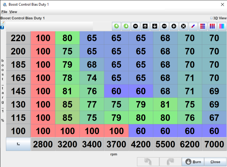
Open loop is simply a term to say that there is no feedback, the system doesn’t try to compensate. All it does is send the duty to the solenoid and hold it open that amount, it is not related to boost in any way – its basically how much the ‘knob’ is open, but controlled by the ECU.
The table is dependent on TPS (How much the throttle is open) and RPM. Using this we can manipulate how quickly the turbo spools, the maximum boost and what boost pressure the system is at any given RPM or throttle position – but its a trial and error process and it will only be correct on that day, in those weather conditions.
When the air is colder it’s denser, there’s more of it for a given area and the engine will ‘spool’ faster and make more peak boost for the same amount of boost duty.
Closed Loop Boost Control is reactive to the inputs, it has a feedback loop. With closed-loop, we have a base duty table – the same as open loop but in this instance, it’s a ‘best guess’ and relates to an additional table which describes the target boost pressure (in KPA).
With this system, we can request a specific boost pressure and the ECU will adjust the boost duty in order to meet that pressure. One added complication is we need to tune how quickly and how aggressively the system reacts to changes
We still have to battle and work around the physical limitations of the system as a whole, asking the system for 12psi at 2000 rpm simply isn’t going to happen if the engine and turbo aren’t sized to deliver that kind of pressure a reasonable pressure at 2krpm at 100% throttle might be 2-3psi on a 1.6l engine.
The impact that has is the system overshooting as it desperately pins the wastegate shut and as the RPMs come up the boost runs away with us a little – matching your boost request to what the system can physically produce will net the best results.
In Simple terms;
Open Loop: Open the valve this much (50%)
Closed Loop: Hey, we’re trying to make 14psi at this rpm at this throttle postion. I think that’ll involve opening the valve this much (say 50%) but if that doesnt make 14psi then adjust the % with this tuned amount of aggressiveness until we get there and modulate it constantly to ensure its correct.
Most boost controllers are just ‘duty’ controllers, i.e. how much the solenoid is open, very little have a feedback loop (closed loop) system to make changes based on the real world outcome.
3 Port Boost Control vs 4 Port Boost Control
If you’re controlling the boost using a single port wastegate where the pressure is only applied to the top of the diaphragm then there is zero reason to use a 4 port electronic boost controller.
The goal of a boost controller is to intercept and change the amount of boost pressure that the wastegate sees, therefore changing the spring rate of the wastegate and the maximum boost pressure.
We control boost by pushing on the top of the diaphragm which in turn pushes on the actuator arm, which opens the flapper diverting gas away from the turbine wheel. Thats the case for internally wastegated turbochargers, external ones we divert the gas before it even gets to the turbo itself.
This pushing action is generated by the pressure the turbo produces, so in a way it’s kind of a reactive system, with a simple system that just uses the physical spring pressure (say 7psi, i.e. it takes 7psi of boost pressure to compress the spring) we will come up on boost kind of slowly and won’t overshoot the pressure.
Thats because as we build boost we have less and less preload on the flapper keeping the gasses all going through the turbine, and it will leak a little bit – slowing down the climb to 7psi, it’s generally a smooth curve to full boost.
When we use a boost controller, we can really aggressively ramp the boost up by applying zero pressure to the wastegate keeping the flapper fully pre-loaded, we then work out the RPM we need to apply pressure to stop it overshooting our target and thats the basis for our open loop duty cycle table.
With a single port wastegate, the rule of thumb is 2.5x the base spring pressure, with a twin port, 6x.
Why is that useful? Well, on it’s own there isn’t anything special about being able to change those numbers – why not just put a spring twice the pressure in it to start with? Traction, thats why. That, and the fact you can’t run less boost than your minimum spring pressure. Whilst you can always double (or more) your boost level by using a boost controller, you cannot HALF it. If your spring is 14psi, you’ll be praying to the gods of traction every time you get on the throttle, as it won’t make LESS than 14*
*When the turbo is in its operating rpm window. It wont be making 14psi at 2000 rpm no matter how hard you press the pedal into the firewall.
It’s generally pretty easy to make power but actually getting it to the ground is the hard part, trying to launch a 14psi boosted MX5 on 195/50/15 tyres is just going to spin them in 1st gear. Where as launching at 5psi, building to 7psi at the top of 1st, then 9ps at the top of 2nd and then the full 14psi thereafter – will get you down the track faster than the guy taking the sledgehammer approach.
With circuit racing being able to use switchable maps, via the Closed Loop system – i.e. asking for a specific boost pressure depending on throttle position and engine RPM – allows you to choose the power for a given track or turn it down to deal with wet weather.
Again, with closed loop we can adjust for changes in ambient air pressure, temperature and heat soak to keep the boost where we need it regardless of factors outside of our control.
3 port solenoids are used in a single port wastegate application but they can also be used in a twin port application.
4 port solenoids are however only used in a twin port wastegate application, as you’re able to add air (boost) to the top of the wastegate increasing its relative spring pressure, as well as leak air from the bottom of the wastegate meaning there is even less pressure below the diaphragm further increasing the relative spring pressure.
